ArbyBot Development Log #1 - Building a CAN protocol with an Arduino & an MCP2515
2,860 words Estimated 15 min read
Introduction
In this post, I’ll present my initial concept for building a communication protocol over CAN for a newer and improved ArbyBot. ArbyBot is a DIY autonomous robot using consumer-grade, off-the-shelf components, including Raspberry Pis and Arduino boards, alongside custom components that I have designed myself. The communication protocol is called ArbyBot CAN (ABC), built atop CAN 2.0B.
The purpose for designing the protocol from the ground up is both as a learning exercise and to have control over the whole protocol.
Acronyms
Acronyms utilised are presented (Table 1).
| Acronym | Definition |
|---|---|
| ABC | ArbyBot CAN |
| ARM | Advanced RISC Machine |
| AWG | American Wire Gauge |
| CAN | Controller Area Network |
| CAN-FD | CAN Flexible Data Rate |
| CAN-XL | CAN Extra Long |
| DFU | Device Firmware Update/Upgrade |
| DIY | Do-It-Yourself |
| ID | Identifier |
| IDE | Integrated Development Environment |
| IP | Internet Protocol |
| LED | Light Emitting Diode |
| LSB | Least Significant Bit |
| MSB | Most Significant Bit |
| OSI | Open Systems Interconnection |
| P2P | Peer-to-peer |
| RISC | Reduced Instruction Set Computing |
| SBC | Single Board Computer |
| SPI | Serial Peripheral Interface |
| SSH | Secure Shell |
| STM32 | STMicroelectronics 32-bit |
| TCP | Transmission Control Protocol |
| UART | Universal Asynchronous Receiver-Transmitter |
| USB | Universal Serial Bus |
| WIP | Work-In-Progress |
Table 1. Acronym definitions.
What is CAN?
Controller Area Network (CAN) is a communication protocol commonly used by embedded devices in vehicles and industrial equipment. A CAN network comprises two or more devices connected over a shared pair of signal wires, CAN-H and CAN-L. CAN does not require a central controller to operate; any node can initiate a transmission. Frames are broadcast across the bus, with each node selecting which to process. Devices can communicate directly without routing messages through a central device.
The CAN protocol provides an arbitration ID and a data payload, both of which can be configured by the transmitting device for use by a higher-level protocol. There are multiple variations of the CAN protocol (CAN 2.0B, CAN FD and CAN XL). CAN 2.0B is the one supported by the MCP2515. Within CAN 2.0B, the arbitration ID can be 11 bits or 29 bits, and the payload is restricted to a maximum of 8 bytes. Both the arbitration ID and the payload segment can be included in the higher-level protocol design.
Goal & Scope
The goal is to define a simple, lightweight communication protocol for the SBCs and microcontrollers used within ArbyBot.
The protocol should meet the following requirements:
- Support at least 30 uniquely addressed devices.
- Allow any device to initiate communication with another device without a central application controller.
- Support both individually addressed and broadcast messages.
- Carry sensor measurements and motor-control commands.
- Support messages spanning multiple CAN frames.
- Be implementable within the memory and processing limits of an Arduino Uno.
- Support bidirectional communication over CAN between an Arduino Uno equipped with an MCP2515 module and an x86-64 computer running Linux with a SocketCAN-compatible CAN adapter.
- Meet the communication deadlines established for the robot’s control functions (future work).
The intended platforms include Arduino Uno, Arduino Mega 2560, Raspberry Pi and other ARM SBCs, and STM32-based boards. The communication hardware and wiring should fit within the space available on ArbyBot.
This article introduces the proposed message format and demonstrates CAN communication between an Arduino and a host computer. The example covers transmission of heartbeat messages. Reassembly and higher-level protocol support remain future work.
Hardware & Prerequisites
The equipment list is presented:
- Arduino Uno R3.
- MCP2515 module.
- USB-to-CAN device (SH-C31G).
- Host computer (assumed to be running Fedora Linux on x86-64).
- 2 x USB-A to USB-B cables.
- 8 x male-to-female jumper wires.
- 2 x wires (roughly 24 AWG) with stripped ends for the CAN-H and CAN-L connections between the MCP2515 module and SH-C31G adapter.
The proposed hardware list reflects what I have available to me now and what the software implementation is designed to support at this stage. I will explore using the MCP2518FD board in future work to make use of larger frame payloads.
For connecting the hardware, a wiring diagram is presented:
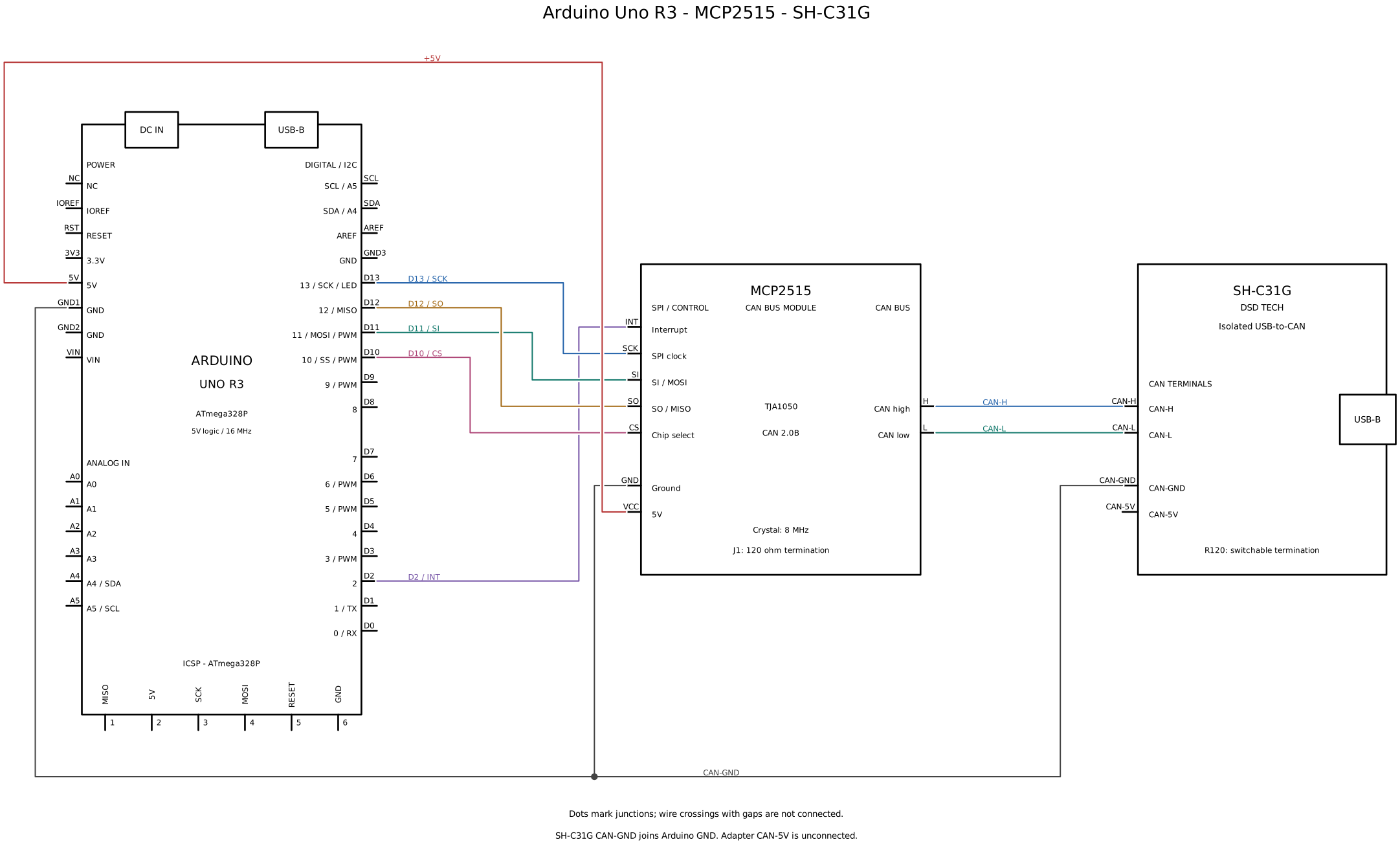
Figure 1. CAN bus wiring diagram featuring the MCP2515, Arduino Uno R3 & SH-C31G.
For ease of reading, a pin-to-pin connection table is presented (Table 2).
| Device A | Pin A | Device B | Pin B |
|---|---|---|---|
| Arduino Uno R3 | 2 | MCP2515 | INT |
| Arduino Uno R3 | 13 | MCP2515 | SCK |
| Arduino Uno R3 | 11 | MCP2515 | SI |
| Arduino Uno R3 | 12 | MCP2515 | SO |
| Arduino Uno R3 | 10 | MCP2515 | CS |
| Arduino Uno R3 | GND | MCP2515 | GND |
| Arduino Uno R3 | 5V | MCP2515 | VCC |
| MCP2515 | CAN-H | SH-C31G | CAN-H |
| MCP2515 | CAN-L | SH-C31G | CAN-L |
| SH-C31G | CAN-GND | Arduino Uno R3 | GND |
Table 2. Pin-to-pin connection list.
Both the SH-C31G and Arduino Uno should be connected to USB ports on the host computer.
Protocol Design
The CAN 2.0B protocol provides the physical and data-link foundations for communication, corresponding to the first two layers of the Open Systems Interconnection (OSI) model. The ABC protocol builds on CAN by defining device addressing, message fragmentation, and payload protocol selection.
The CAN frame exposes two primary binary data segments: the arbitration ID and the data payload. The addressing and message-handling layer will use only the arbitration ID for its metadata. An extended arbitration ID of 29 bits will be used instead of the standard 11-bit identifier.
The ABC protocol builds upon the two-layer CAN protocol by describing an adaptation layer that can be used to support additional protocols held within the payload data segment. A placeholder protocol will be defined to test the transport: a zeroed-out payload communicating a heartbeat or signal of life. Future work will determine how to transport Internet Protocol (IP) packets across the CAN bus.
The protocol layers are listed (Table 3).
| Layer | Responsibility | Implementation |
|---|---|---|
| 1. Physical - OSI layer 1 | Electrical signalling, bit timing, wiring and termination. | CAN transceivers, CAN-H/CAN-L wiring and terminating resistors; the MCP2515 handles bit timing and synchronisation. |
| 2. CAN data link - OSI layer 2 | CAN frame structure, identifiers, arbitration, acknowledgements and error handling. | The MCP2515 CAN controller. |
| 3. ABC - Addressing and message handling | Identify senders and destinations, select the payload protocol, and split messages into packets with metadata for reassembly. | The arbitration-ID format, ID encoders/decoders and fragmentation logic. Receiver-side reassembly remains future work. |
| 4. Application payload | Define the meaning and binary encoding of message contents: command codes, parameters and sensor values, including their data types, byte order and units. Interpret received messages using the selected payload protocol. | Arduino and Python payload encoders, decoders and command handlers. The initial convention is a heartbeat of eight zero bytes under protocol 0; sensor and motor-command formats remain to be defined. |
Table 3. The layers of CAN 2.0B, ABC and the Application Payload.
A flowchart is presented (Figure 2) showing a visualisation of the proposed protocol stack.
---
config:
    flowchart:
        wrappingWidth: 1000
        rankSpacing: 32
        padding: 10
        subGraphTitleMargin:
            top: 6
            bottom: 16
---
flowchart TB
    accTitle: Four-layer CAN communication stack
    accDescr: A diagram showing the four layers of the proposed communication stack.

    subgraph Custom["<span style='white-space:nowrap'>Proposed Communication Stack</span>"]
        direction TB
        L4["<div style='width:800px'>4. Application payload - Heartbeats, sensor data, motor commands</div>"]
        L3["<div style='width:800px'>3. ArbyBot CAN - Addressing and message fragmentation</div>"]
        L4 --> L3
    end
    subgraph CAN["<span style='white-space:nowrap'>Controller Area Network (CAN 2.0B)</span>"]
        direction TB
        L2["<div style='width:800px'>2. CAN data link - Frames, arbitration, error handling</div>"]
        L1["<div style='width:800px'>1. Physical - Signalling, CAN-H/CAN-L, termination</div>"]
        L2 --> L1
    end

    Custom --> CAN

    style Custom fill:none,stroke:#93a1a1,stroke-width:1px,stroke-dasharray:2 4
    style CAN fill:none,stroke:#93a1a1,stroke-width:1px,stroke-dasharray:2 4
    classDef layer stroke:#93a1a1,color:#586e75
    class L1,L2,L3,L4 layer
    style L4 fill:#eee7f1
    style L3 fill:#e4edf0
    style L2 fill:#e7eedf
    style L1 fill:#f4e6d5
Figure 2. Protocol layer flowchart.
Arbitration ID Format
The arbitration ID identifies the intended recipient, the sender, the payload protocol and the message priority. Lower priority values take precedence during arbitration.
The term packet will be used in place of CAN frame. A message comprises one or more packets sharing the same sender, destination, protocol and message counter. Each message carries application data that the receiver reconstructs from its constituent packets.
The packet index increments modulo 32 within a message, allowing the receiver to check the expected sequence. The first and last flags identify the message boundaries. The message counter remains constant throughout a message and increments modulo 8 for each new message. Packets belonging to a message must be transmitted in sequence, beginning with the first packet. A sender must not reuse a message counter while packets from its previous use remain pending for transmission. Upon receipt of a first packet, the receiver should discard any incomplete message with the same sender ID, target ID, protocol and message counter, and begin assembling the new message.
The proposed arbitration ID format is presented (Table 4). Bit offsets count from zero at the most significant bit (MSB). Bit positions count from zero at the least significant bit (LSB), matching the positions used in the software.
| Bit offset | Bit position | Size | Name | Data Validation | Description |
|---|---|---|---|---|---|
| 0-1 | 28-27 | 2 bits | priority |
Integer: 0-3. | The message priority determines collision arbitration on the network, wherein a lower value takes precedence. |
| 2-4 | 26-24 | 3 bits | protocol |
Integer: 0-7. | The payload protocol informs the recipient what the data or protocol looks like within the payload body. |
| 5-11 | 23-17 | 7 bits | target_id |
Integer: 0-127. | The destination of the packet informs recipients whether to discard a message. There are 128 possible address values, with 0 reserved for broadcast to all devices. |
| 12-18 | 16-10 | 7 bits | sender_id |
Integer: 1-127. | The sender ID identifies the origin of the packet and is limited to 127 devices due to the reservation of the 0 value. |
| 19-21 | 9-7 | 3 bits | message_counter |
Integer: 0-7. | The message counter informs the receiver which packets belong to the same message and increments for each message sent. The counter retains the same value when the packet index wraps around. |
| 22-26 | 6-2 | 5 bits | packet_index |
Integer: 0-31. | The packet index identifies which part of a message the payload belongs to and the expected sequence in which the packets are to be reassembled. This value wraps around for messages which are longer than 32 packets. |
| 27 | 1 | 1 bit | is_first_packet |
Integer: 0-1 treated as a boolean. | The first packet signifies the starting packet of a message, sent by a transmitter. |
| 28 | 0 | 1 bit | is_last_packet |
Integer: 0-1 treated as a boolean. | The last packet signifies the final packet of a message, sent by a transmitter. If all packets were received in order from the first packet to the last packet, the message can be reconstructed by the receiver; otherwise, it can be discarded. |
Table 4. Proposed Arbitration ID format.
A packet diagram visualising the fields of the Arbitration ID in order is presented (Figure 3), written with the MSB first.
---
title: ABC Arbitration ID — 29 bits
config:
    packet:
        bitsPerRow: 29
        bitWidth: 32
        showBits: true
---
packet
    accTitle: Fields of the 29-bit ABC arbitration ID
    accDescr: An ABC arbitration ID consisting of a priority, protocol identifier, target device ID, sender device ID, message counter, packet index and first/last bits.
    0-1: "Priority"
    2-4: "Protocol"
    5-11: "Target ID"
    12-18: "Sender ID"
    19-21: "Counter"
    22-26: "Index"
    27: "F"
    28: "L"
Figure 3. Arbitration ID Packet Diagram.
A single-packet message sets both the first and last flags. The receiver should discard an incomplete message if it detects an unexpected packet index or a reassembly timeout. There exists an edge case for message completeness in which the loss of 32 consecutive packets within a message could go undetected by the receiver, because the packet index wraps around to the expected value. If no other check detects the loss, the receiver could reassemble and accept the message with missing data.
The proposed protocol was based on the open source CubeSat Space Protocol v2 or libcsp.
Changes include:
- destination addresses limited to 7 bits (0-127).
- sender addresses limited to 7 bits (1-127).
- destination
0designated as broadcast to all listeners, with sender0prohibited. packet_countandframe_countwere renamed tomessage_counterandpacket_indexwith extra bits added for increased packet loss detection.
Test Case
The first test case of the proposed protocol will verify reception of broadcast heartbeats.
A heartbeat will be defined in this test as 8 bytes of zeroed data: [0x00, 0x00, 0x00, 0x00, 0x00, 0x00, 0x00, 0x00].
- Each device will independently broadcast a heartbeat every two seconds while listening for incoming packets.
- Each device will log heartbeats that it hears to the console for inspection.
- Each device will listen to any sender ID emitting to target ID
0(broadcast). - Each device will transmit the heartbeat using target ID
0(broadcast) and its sender ID defined as:- Host computer:
27. - Arduino:
49.
- Host computer:
The Arduino’s log output will be visible in the serial monitor (within the Arduino IDE), and the host’s output will be visible in the terminal running the Python client.
A sequence diagram is presented, showing the pattern of communication between the Arduino and the host computer (Figure 4). Time runs downwards. Each arrow represents a broadcast packet observed by the other node; the parallel sections represent independent tasks.
sequenceDiagram
    accTitle: Independent CAN heartbeats
    accDescr: The Arduino and Linux host independently broadcast heartbeats every two seconds and log received heartbeats. Neither heartbeat is a reply.
    participant A as Arduino Uno<br/>ID 49
    participant H as Linux host<br/>ID 27

    Note over A,H: Independent timers<br/>Shared CAN bus

    par Arduino heartbeat task
        loop Every 2 seconds
            A->>H: Broadcast heartbeat<br/>Sender 49 · eight zero bytes
            Note over H: Log received<br/>heartbeat
        end
    and Host heartbeat task
        loop Every 2 seconds
            H->>A: Broadcast heartbeat<br/>Sender 27 · eight zero bytes
            Note over A: Log received<br/>heartbeat
        end
    end

    Note over A,H: One packet on the bus at a time.<br/>Simultaneous attempts<br/>are resolved by arbitration.
Figure 4. Heartbeat test sequence diagram.
Both heartbeat tasks will run concurrently, but packets will occupy the shared CAN bus sequentially. If the devices attempt to transmit at the same time, CAN arbitration will determine which transmission proceeds first.
Procedure and success criteria
- Configure and bring up the host’s
can0interface at 125 kbit/s, then start the Arduino and Python client. - Open the Arduino serial monitor at 115200 baud and observe the Python terminal alongside it.
- Once both devices are running, let the test continue for at least 30 seconds to exercise message-counter wraparound.
- Confirm that both consoles repeatedly log heartbeats from the other device, approximately two seconds apart, while both devices continue sending their own heartbeats.
- Check each sender’s received counter sequence for progression from 0 through 7 and back to 0. Compare available transmission and reception logs, and record any gaps, timing anomalies, or reported errors. A transmit-side log alone is not proof that the other device received the packet.
This test will demonstrate bidirectional single-packet communication under the test conditions. It will not establish delivery guarantees or latency limits under heavier bus traffic.
Implementation
A set of test scripts was developed to demonstrate the proposed protocol using the Arduino Uno R3, MCP2515 CAN module, and SH-C31G adapter. The following section describes the experimental setup and the scripts used to exercise the protocol.
The instructions are provided “as is” as a rough guide to configuring this setup. No warranty is provided, and no guarantee is made that these instructions are correct or will be maintained. This is purely for informational purposes.
Hardware
The MCP2515, Arduino Uno R3 and SH-C31G USB-to-CAN interface should be connected as described in Table 2 (illustrated in Figure 1). The Arduino Uno R3 and SH-C31G should be connected via their USB-B ports to USB ports on the host computer.
Check that the Arduino’s green power LED and the MCP2515 module’s red power LED are illuminated.
Ensure that the SH-C31G has not booted into DFU mode. On the adapter used here, normal operation is indicated by one red LED and two green LEDs. If only the red LED is illuminated, unplug and reconnect the USB cable, then check the indicators again.
Software
The software provided is a work-in-progress (WIP) implementation and therefore incomplete at this stage, but is sufficient for demonstrating the functionality of transmitting and receiving heartbeats between the Arduino and host computer.
Arduino
Configure the autowp/arduino-mcp2515 library for use within the Arduino IDE.
Once you have confirmed that the Arduino is connected to the Arduino IDE, upload the Arduino script (Code Snippet 1).
Set the serial monitor baud rate to 115200 to view its output.
An 8 MHz oscillator is assumed by the provided software, update as required.
1 | |
Code Snippet 1. Arduino MCP2515 heartbeat sketch.
Both received-packet and outgoing-packet logs use the same bounded queue, drained only when serial buffer space is available.
QUEUED indicates that the MCP2515 accepted a transmission request; it does not confirm transmission completion or reception by another device.
To determine that it is working, monitor the serial output and compare it with the output recorded in the demonstration section.
USB-to-CAN (SH-C31G)
For the host computer to communicate with the USB-to-CAN interface, SocketCAN must be configured and the CAN interface brought online:
1. Install the utilities
Open a terminal and use dnf to install iproute and can-utils on the host computer running Fedora Linux:
1 | |
2. Connect the USB CAN adapter and identify its interface
1 | |
An interface named can0 should be listed, indicating that Linux has recognised the CAN adapter.
It may initially be shown as DOWN.
3. Configure the bitrate and enable the interface
1 | |
4. Check the configuration and listen for traffic
1 | |
Check that the interface is UP and reports bitrate 125000.
If the Arduino has already been configured, you should see CAN frames appearing in the terminal.
More information can be found in the can-utils software documentation.
These settings need reapplying after a reboot or disconnect unless you configure persistence.
Python Client
The Python client comprises two files: gateway.py and main.py.
The Gateway provides a class with various useful methods for sending and receiving data via the USB-to-CAN interface using the python-can library.
The main.py script is the entry point to the program, which starts the loop for sending the heartbeat via the Gateway.
The file gateway.py is provided:
1 | |
Code Snippet 2. gateway.py.
The file main.py is provided:
1 | |
Code Snippet 3. main.py.
Save these files to a folder, make sure Python 3 version 3.10+ is installed and accessible in a terminal, and install python-can.
Then, launch main.py:
1 | |
Demonstration
An example of the Arduino serial console log is presented:
1 | |
An example of the Python client console log:
1 | |
Conclusion
The heartbeat testing was successful, but the implementation was limited to proving the heartbeat concept only.
The progression will be to:
- a) Migrate to CAN-FD to increase data rates for better throughput and larger payloads for carrying IP packets.
- b) Swap out the Arduino Uno R3 in favour of faster hardware in my possession: a Pi Pico or Nucleo-H743.
- c) Define protocol
0to support transmitting sensor data, setting motor speed and direction, and configuring device settings. - d) Implement message reassembly, including checking the packet sequence and handling timeouts.
- e) Define and implement protocol
1to support IP packets and TCP communication. - f) Configure and test the use of some example sensors and actuators over the CAN bus.
- g) A formal design document for ABC.